MEDIAART 2G03: Microphones
Microphone constructions
Dynamic microphones
One of the major types of microphones that we are likely to encounter is the dynamic microphone. The dynamic microphone is basically a coil that has been connected to a diaphragm that gets moved by the air, and the coil is around a magnet, and when the diaphragm makes the coil move in relation to the magnet, a tiny electrical signal is generated. This is basically like a little electrical generator, and you get more or less electricity depending on how much the diaphragm moves. It's also kind of like a loudspeaker in reverse; a loudspeaker is often built by having a coil and a magnet, and electricity is applied to the coil to make the diaphragm move. So the dynamic microphone is kind of like a reverse loudspeaker.
And the main advantage of this way of building microphones is that they're quite robust to damage. These [dynamic microphones] can be built in really solid ways. And so you commonly see dynamic microphones used for example, in live sound reinforcement, like when a band is playing on stage, that's a fast-moving environment with lots of potential for damage. There's lots of dynamic microphones typically in those situations. It's probably not going to be the end of those microphones if they're dropped on stage. You also see dynamic microphones used quite a lot in video production work where people are moving about the world with video cameras and the like, and there is some potential there for impact with the microphone. So by using dynamic microphones, which are fairly robust to damage, the equipment is a bit safer than it might otherwise be.
Condenser microphones
But there's another major kind of microphone, and it's the kind of microphone that we're probably going to use most of the time in our projects in this course, and that's the condenser microphone. It works on a different electrical principle. We still have a diaphragm that gets moved by the air, but in the condenser microphone, the diaphragm is connected to one of two metal plates that are close to each other, but not touching. And a voltage is applied to the plates, and that voltage is not able to cross the plates because they're not touching. But as the plates get slightly closer together or slightly further apart, we're able to sense that change in the charge across the two plates. And the word for this type of microphone (condenser microphone) basically comes from the fact that the word "condenser" is an older (and rather British) word for what is also called a "capacitor" (the electrical component). A capacitor is an electrical component where we have two charged areas fairly close to each other but not touching. So the main advantage of this kind of microphone is that it provides fairly detailed capture of high frequencies at a relatively low price. We can make dynamic microphones that also provide detailed capture of high frequencies, but it tends to cost a lot more to do that. And these microphones [condenser microphones] also have a key disadvantage, which is that they're quite fragile, because the two plates have to be very close together but not touch for the microphone to work. Dropping the microphone or banging it could cause the two plates to touch or to become too far apart as well, and the microphone's not going to work anymore. They're also very sensitive to moisture, because if water particles get in the very tiny space between the two plates and connect them electrically, then obviously that is not going to work anymore.
So condenser microphones give us a relatively detailed capture of high frequencies, often something we want in order to create very visceral recordings that have a sense of intimacy and closeness and physicality. But the disadvantage of this principle is that they're very fragile – they're microphones that we have to take great care of.
Other microphone constructions
There are a few other microphone constructions to mention briefly. The ribbon microphone, one of the earlier principles with which microphones were built, is a little ribbon of metal suspended between two magnets that generates electricity (a little bit like a dynamic microphone). Ribbon microphones are making a comeback, and tend to be somewhat expensive, but you're starting to see them being used in high-end audio work again.
There's also the electret condenser microphone, which is a very cheap microphone. This is often the kind of microphone that is built into smartphones and laptops, and things like this.
There's also the piezoelectric microphone, which is formed by putting two different metals in close conjunction with each other, and a tiny electrical voltage is generated when the combined element of the two metals flexes a little bit. So there are these other microphone constructions.
For our purposes in this course, we're mostly going to be using the condenser microphone for its detailed capture of high frequencies.
Microphone directionalities
Omnidirectional
On the image immediately below, we have an example of what is called a microphone polar pattern, which is a graph of how sensitive a microphone is in different directions. And the way these graphs work, there's always a direction that is labeled zero degrees (often, but not always, it's pointing up on the graphs), and zero degrees is what we can think of as the front of the microphone, the way the microphone is pointed perhaps. And then as we go around the circle, this will be to the right. And then as we keep going around the circle to 180 degrees, we'll be in exactly the opposite direction of the front of the microphone. If we keep going around we'll come to the left, and if we keep going around, we'll come back to the front again. And this direction that I've been calling "front" here (the zero degree direction), is also often called the "on axis direction" for the microphone. And as we go around the circle, further and further away from the on axis direction, we can also say that we're going increasingly off axis.
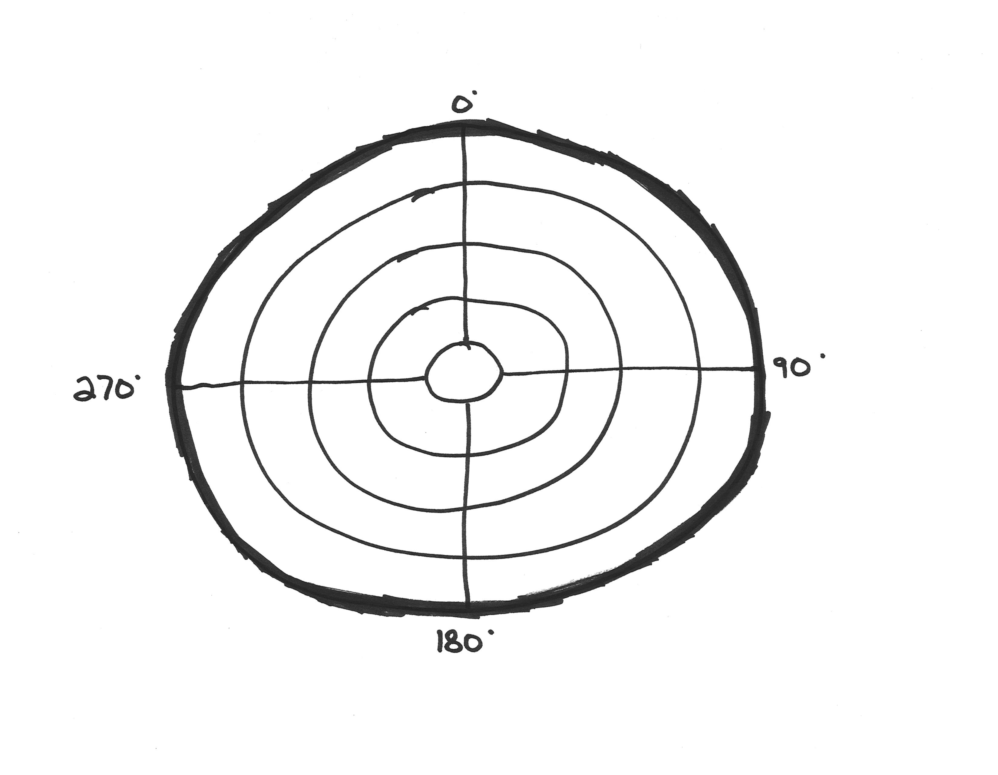
That graph (above) is the graph of one really common and basic type of microphone in terms of directionality, the omnidirectional microphone. And the thick line shows how sensitive this microphone is in different directions. The thick line is in the same place on the circle, it's the same distance away from the center of the circle all the way around. And this reflects the fact that omnidirectional microphones are microphones that are equally sensitive in all directions.
Cardioid
Here (below) is the polar pattern for another very common basic type of microphone directionality: the cardioid microphone:
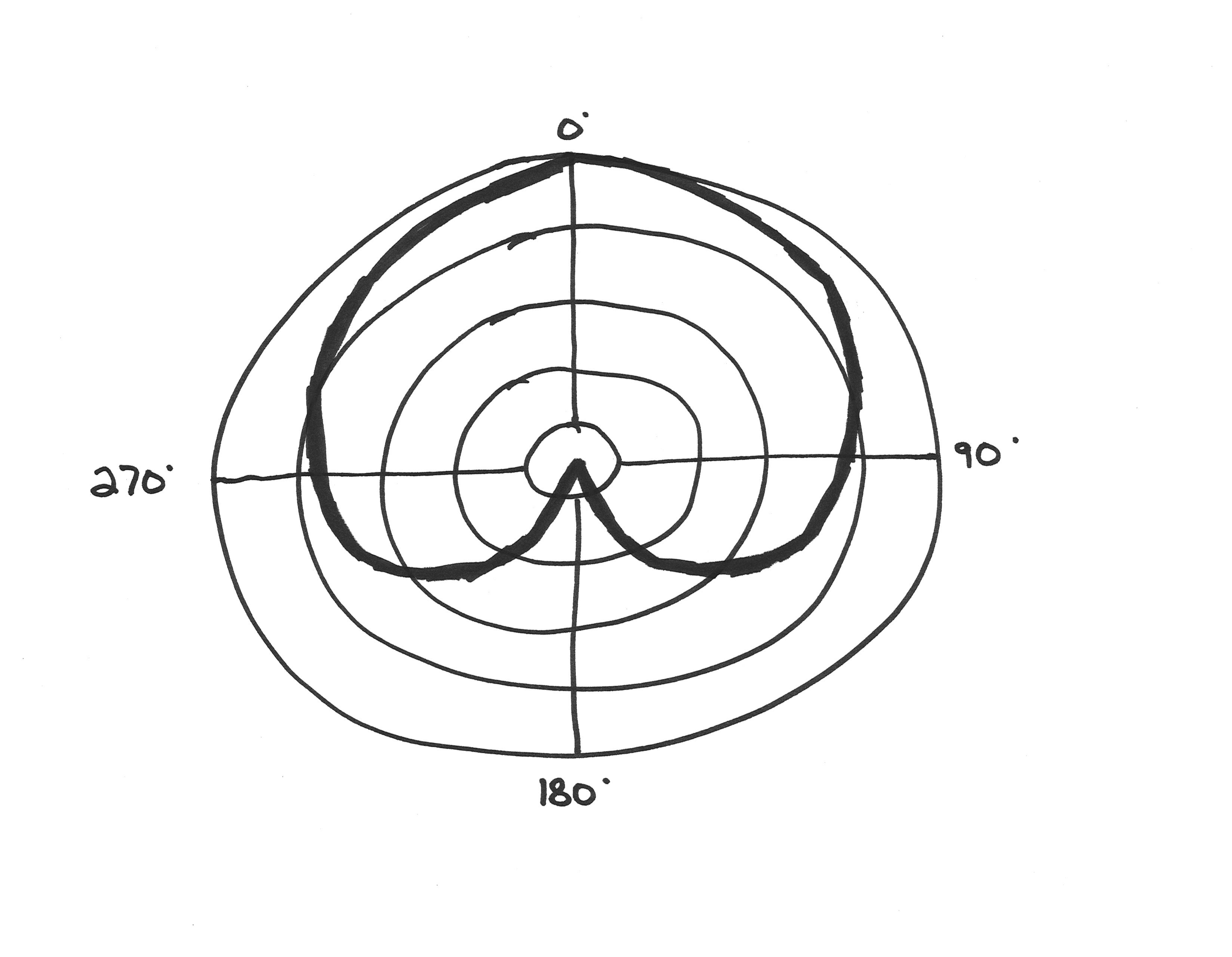
The reason it's called cardioid is basically because if we take the shape of the thick line showing its sensitivity, it looks like an upside-down heart. And things that have cardio in them are things that have to do with the heart, so it's as simple as that. And the cardioid microphone is the basic type of directional microphone. So if we follow its sensitivity, it's at maximum sensitivity in the “on axis” direction. And then as we come around say to the left, by the time we've gotten to 90 degrees to the left (or 270 degrees), that sensitivity line has come in just a little bit over one band on the circle, so the microphone is less sensitive in this direction. And typically with the cardioid microphone, we'll be somewhere between five and ten decibels less sensitive as we come around to the left or right sides. And then as we keep going around, towards the back it gets less sensitive still, and by the time we're off axis, we're at a minimum sensitivity.
An important thing to realize about this, is that the minimum sensitivity of the microphone (the minimum sensitivity of this cardioid microphone when we are 180 degrees off axis), is not going to be minus infinity decibels. It's not going to completely eliminate sounds that come from this direction; it's probably going to reduce them by somewhere in the neighborhood of 25 to 30 decibels (only). An important consequence of this is that a directional microphone like this doesn't eliminate things anywhere, it just reduces them by different extents depending on the direction.
These are two basic directionalities of microphones here that we're going to encounter and use a lot in this course: Omnidirectional microphones are equally sensitive in all directions, while cardioid microphones get progressively less sensitive as you move from the on axis front of the microphone, to the off axis rear of the microphone. But there are a few others it is useful to know about...
Super-cardioid
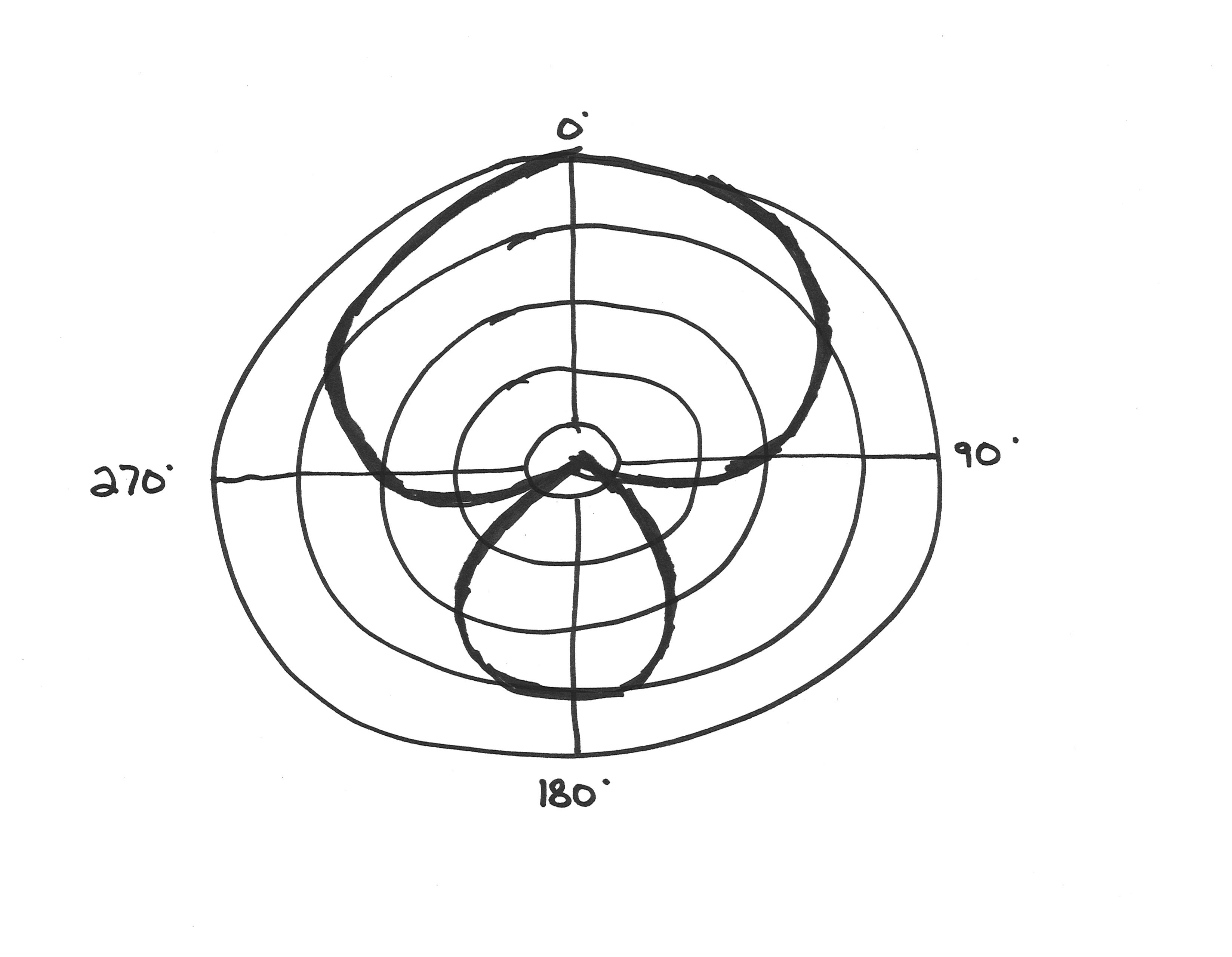
So here (image below) we have the super cardioid directionality, and as you might expect, the super cardioid directionality is kind of like an exaggeration or intensification of what we saw on the polar pattern for the cardioid microphone. So basically what makes a super cardioid directional microphone, is that as we come off axis, the sensitivity reduces somewhat faster than the cardioid microphone. So we start to suppress sounds a little more quickly as we come off axis, but the price of this increased directionality is that we start to become more sensitive again behind the microphone. So it's kind of like the sensitivity comes down and down and down as we come towards the left, but then as we go away from the left towards the back, it starts to increase again. And it never quite becomes as sensitive as it was in the front, but it gets kind of close, and then the same pattern repeats itself as we come back up again around the right side. So the uper cardioid microphone is somewhat better at suppressing things to the left and right than the cardioid microphone is, at the price of some increased sensitivity behind the microphone.
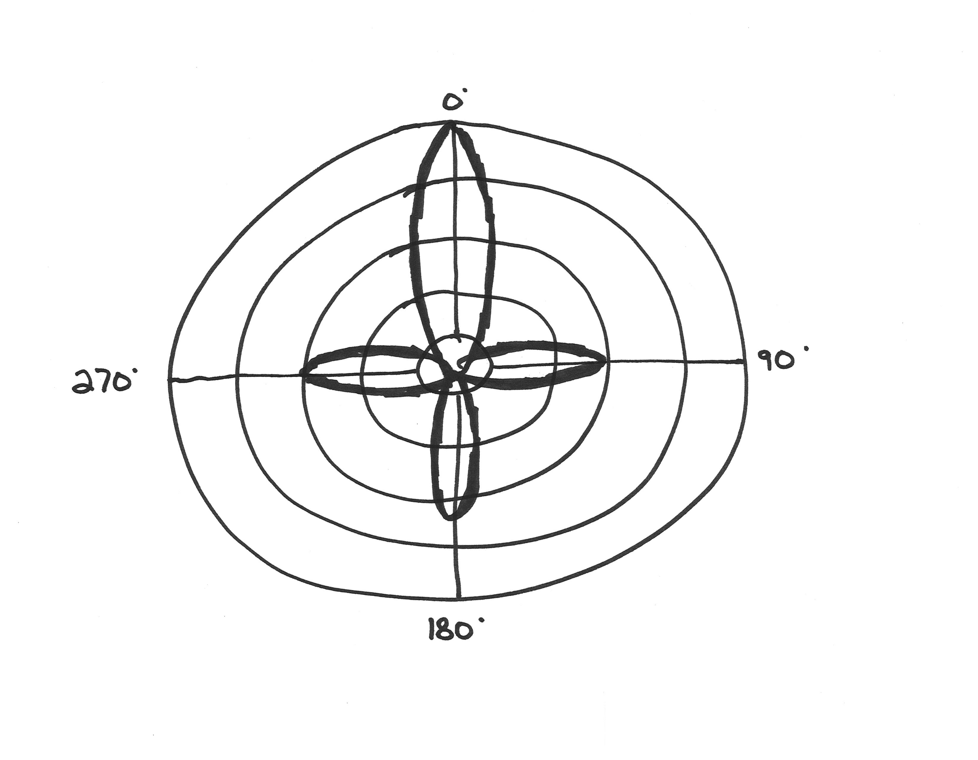
And we'll see a kind of similar thing here (image below) with the most directional microphone of all, the shotgun or lobar microphone. In the polar pattern for the shotgun or lobar microphone, starting from the on axis position, as we come around to the left, the sensitivity goes down really really really fast. But the price of this is that when we are right at the left, it comes up again. It doesn't come up to the zero decibel mark (no change), it doesn't come up to be as sensitive as it was at the front, but it does come up. It is more sensitive again when we're directly at a right angle to the front of the microphone. And then it reduces again, and then the same pattern happens again when we're 180 degrees off-axis, there's some increased sensitivity again. And then again when we're ninety degrees to the right, there's some increased sensitivity again. So the shotgun microphone is useful for pointing right at things, but we're going to have to remember that we're probably going to pickup reasonably well some things that are directly to the right, directly to the left, and directly behind the microphone.
One final, common directionality to talk about that we're going to encounter, is the figure-8 microphone:
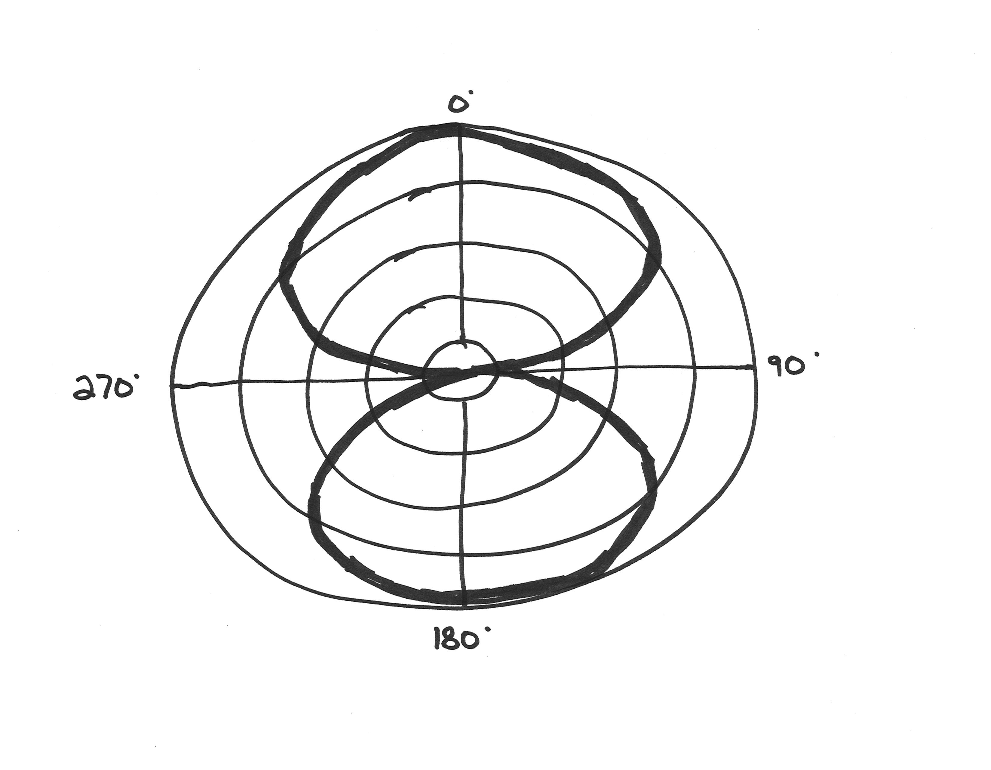
And this is a microphone that is equally sensitive in two opposite directions. At the zero degrees, or the on axis position, it is maximally sensitive. And the sensitivity comes down as we move to the right of the microphone, but then as we come back out of the right of the microphone towards the rear, it increases again. And when we get to the rear of the microphone (the 180 degree off axis position), it is just as sensitive as it was in the front, and then the same pattern repeats on the other side.
(All of these directionalities are useful in particular situations, but in this course we're probably going to get the most use out of the omnidirectional and cardioid patterns, still.)
Sometimes microphones are made with a fixed pattern. Many microphones are just an omnidirectional microphone, or they're just a cardioid microphone, or they're just a shotgun microphone. However, there are also what we call multi-pattern microphones, that are able to produce different types of directionalities, and so are able to be used in different ways. Here's a picture of an AKG C414 microphone, a really wonderful studio reference microphone:
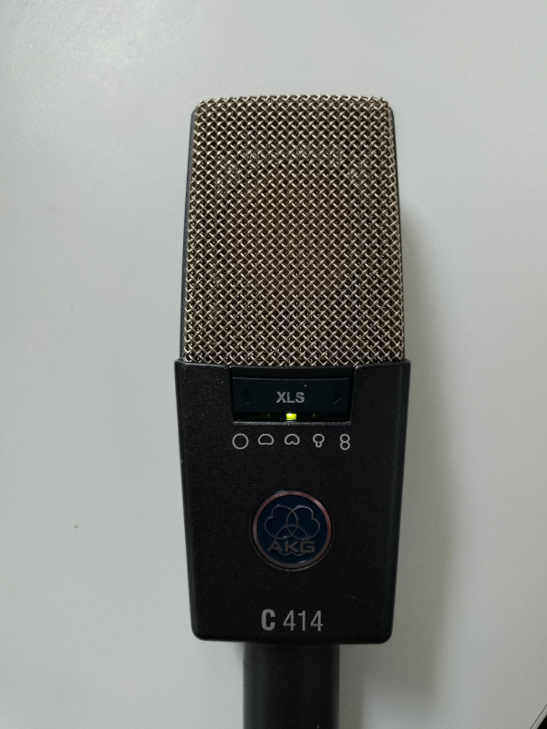
And on the front of the AKG C414, there's this mode switch, and below the switch, there are little diagrams (right now the one in the middle is the one that is lit up in green). And these diagrams are basically little pictures of the polar pattern diagrams. On the left, there is the omnidirectional polar pattern, just an even circle all the way around. Here in the middle (the one that's currently selected), that's a cardioid pattern, looks like an upside-down heart. And then here next to the heart, we have something that looks like that super cardioid, also sometimes called "hyper cardioid pattern." And then over here on the far right, we have the figure-8 pattern, and it looks like a number eight. And so the only one we didn't talk about is this one over here (the second one from the left), and that's basically something that's kind of halfway between omnidirectional and cardioid, and it's a mode that is somewhat unique to this microphone.
I want to conclude this section with two tips:
Tip number one (and we've already hinted at this) is that because the polar patterns of microphones show us that we're never completely eliminating the sensitivity (it's never minus infinity), we should think of directional microphones as reducing things in certain directions. But we shouldn't think of them as simply pointing at things or as eliminating things completely, because that's not what the polar patterns show us they're doing.
And the second tip is actually to use omnidirectional microphones (the one that is equally sensitive in all directions) whenever possible (which is not always, to be clear). After all, we have other strategies for dealing with noise. So when we have everything under control with those other strategies, we might get somewhat more natural, somewhat more realistic recordings, recordings that are more responsive to things that come from different directions (as sounds often do), when we use omnidirectional microphones.
Phantom power
So the dynamic microphone doesn't need power because as we saw, being composed of a magnet and the coil, it is itself a generator of electricity. But condenser microphones do need power; they need some way of charging up those two plates that are so close to each other, and they can get this from a couple places. They can get them from some kind of battery system that's built into the microphone, or maybe they get it from some kind of special power supply that is designed specifically for that microphone... but the most common way of getting power to condenser microphones is something called phantom power.
The reason it's called phantom power is because we don't need any extra cables other than the microphone cable we're already using to get power to the microphone. The power that we're using to make this microphone work, and the signal that we're getting back from the microphone, coexist in the same cable, and so that's why it was called phantom power.
It's usually abbreviated 48V, which stands for 48 volts, because there is a standard that expects phantom power to be at, or around, 48 volts. That said, it is possible for many microphones to work with lower voltages. And you will encounter field recorders where you can deliberately pick lower voltages in order to save batteries. And sometimes, that's something that you can experiment with if the microphone works at lower voltage and you need to use lower voltage.
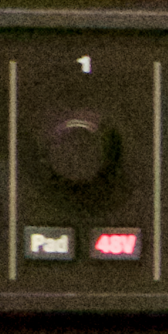
The image below is a picture of the front of an audio interface (the MOTU 8M audio interface), and it shows the knob/dial where the gain for the preamplifier on microphone channel 1 is set. And just below it, we see a little button that's lit up and that says “48V” - that’s the button where we're able to turn phantom power on or off for this microphone channel.
You'll also encounter audio interfaces where phantom power gets turned on for all of the microphone inputs at once, or for some selection of them, like 1 to 4 or 5 to 8.
So the last thing we need to realize about phantom power, is that we are putting a relatively high voltage into our microphone cables when we turn it on, and so it's important that we don't turn on phantom power for things that don't need phantom power. Providing phantom power to something like a dynamic microphone, a guitar, or some kind of keyboard synthesizer, or something like that, could do a lot of electrical damage, either to that device or to your microphone preamplifier, or both. Really, we're only using phantom power for things we know need phantom power, most typically, condenser microphones.
Balanced signals and XLR cables
When we send signals over electrical cables, they tend to accumulate noise from background electromagnetic radiation. And typically this sounds like a kind of hiss. And this hiss comes from the fact that as our signal is traveling over that long metal cable, every point along that cable is also being affected by random radio frequency or audio frequency things that are happening (random bits of electromagnetic radiation).
Let's imagine we're trying to send the signal on the left [in the image below] from a microphone to a preamplifier, with a metal cable. If we were sending this just over a single electrical cable, the signal wouldn’t arrive with the exact same shape. The received shape would be kind of like the original shape, except it would be randomly deflected up and down in different amounts at each point in time, depending on what was going on with the background electromagnetic radiation. And we might hear all those little random deflections as a “hiss”.
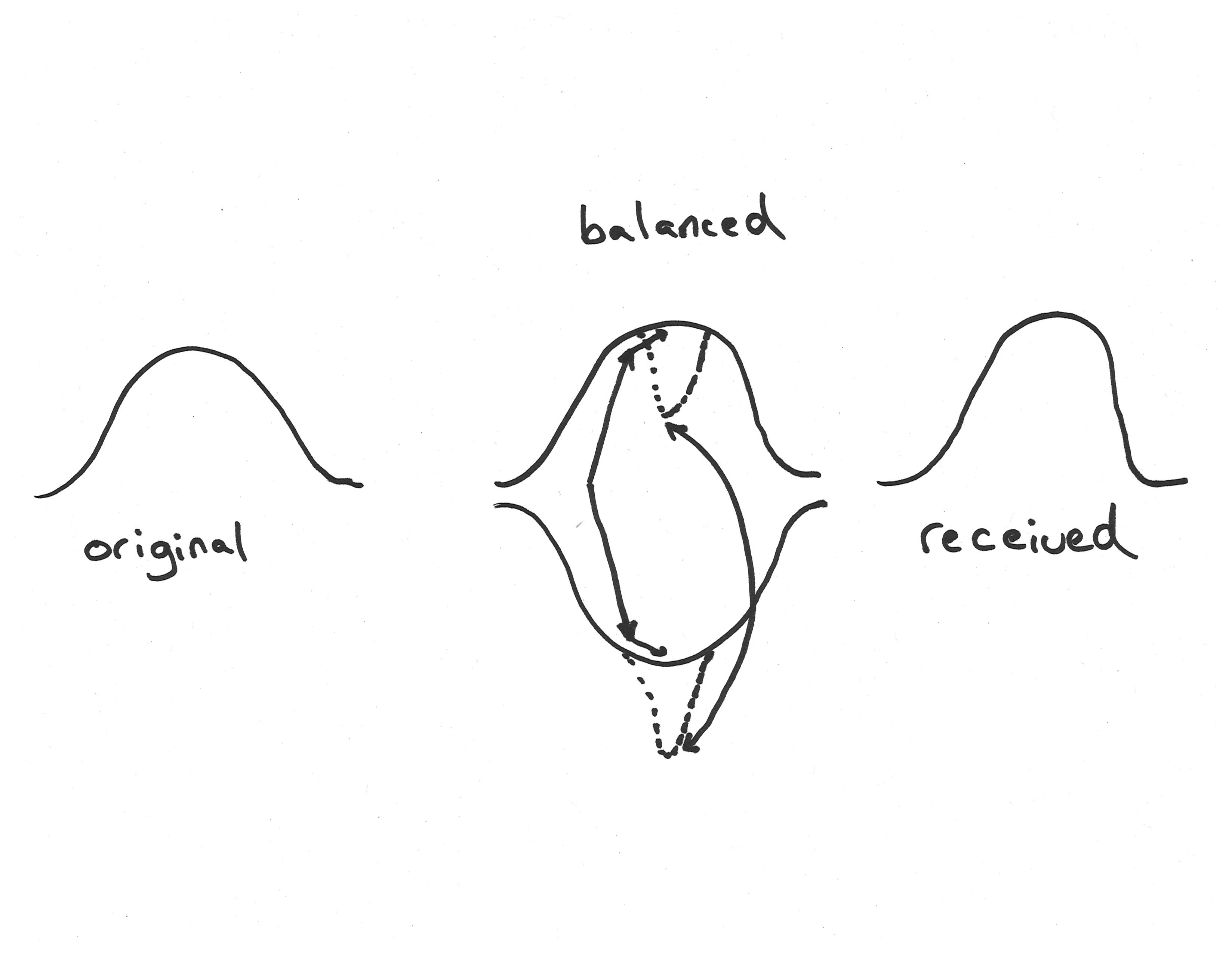
Balanced signals are a really strong method for addressing this problem and reducing that electrical noise. And the way it works is that we send the signal and we also send the opposite of the signal (like the signal inverted at the same time), using a different metal wire. And then at the point of reception, what we do is we take the difference between those two signals, and we use that to reconstruct the original signal. If you think about it, as the original signal gets higher, the opposite signal gets lower, and also the difference between these two signals gets bigger. So the difference between the two signals is still proportional to the original.
Now imagine that something happens, some stray cosmic event, some piece of electromagnetic radiation goes through that cable in a strong way at a particular point, and imagine that it pushes the original signal down a bit. In our balanced signal, it's going to do that to both of those signals (the original and the opposite) in the same direction (since the two wires are basically in the same place). Meanwhile, the difference between the two signals stays the same. And so when we use those two signals to reconstruct the original signal, we still get back the original as if the electrical noise didn’t interfere.
That's the basic way that balanced signals work, and it requires that our cables have three threads of metal in them. One is for the signal, one is for the opposite of the signal, and the third one is a "ground" that is electrically necessary as a place where all of the electricity can return to when we're done with it.
So this brings us to the typical microphone cable, also known as the "XLR cable." Such cables have plugs (things with pointy pieces of metal in them) and sockets (things with holes for pointy pieces of metal) with three prongs/holes, and look like this [image below].
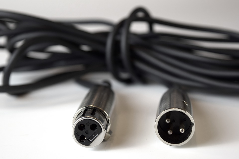
And so now perhaps we can understand why there are three different connections of metal that are made through this cable. One is for the signal, one is for the opposite of the signal, and the third one is for the electrically necessary ground.
XLR cables or microphone cables are useful for a number of reasons. Not only are they capable of carrying a balanced signal from a microphone to an audio interface, but they're also capable of being used as their own extensions. This is because one end of the cable is a plug, and the other end of the cable is a socket, which means we can put multiple of these cables together to make a longer cable without much fuss.
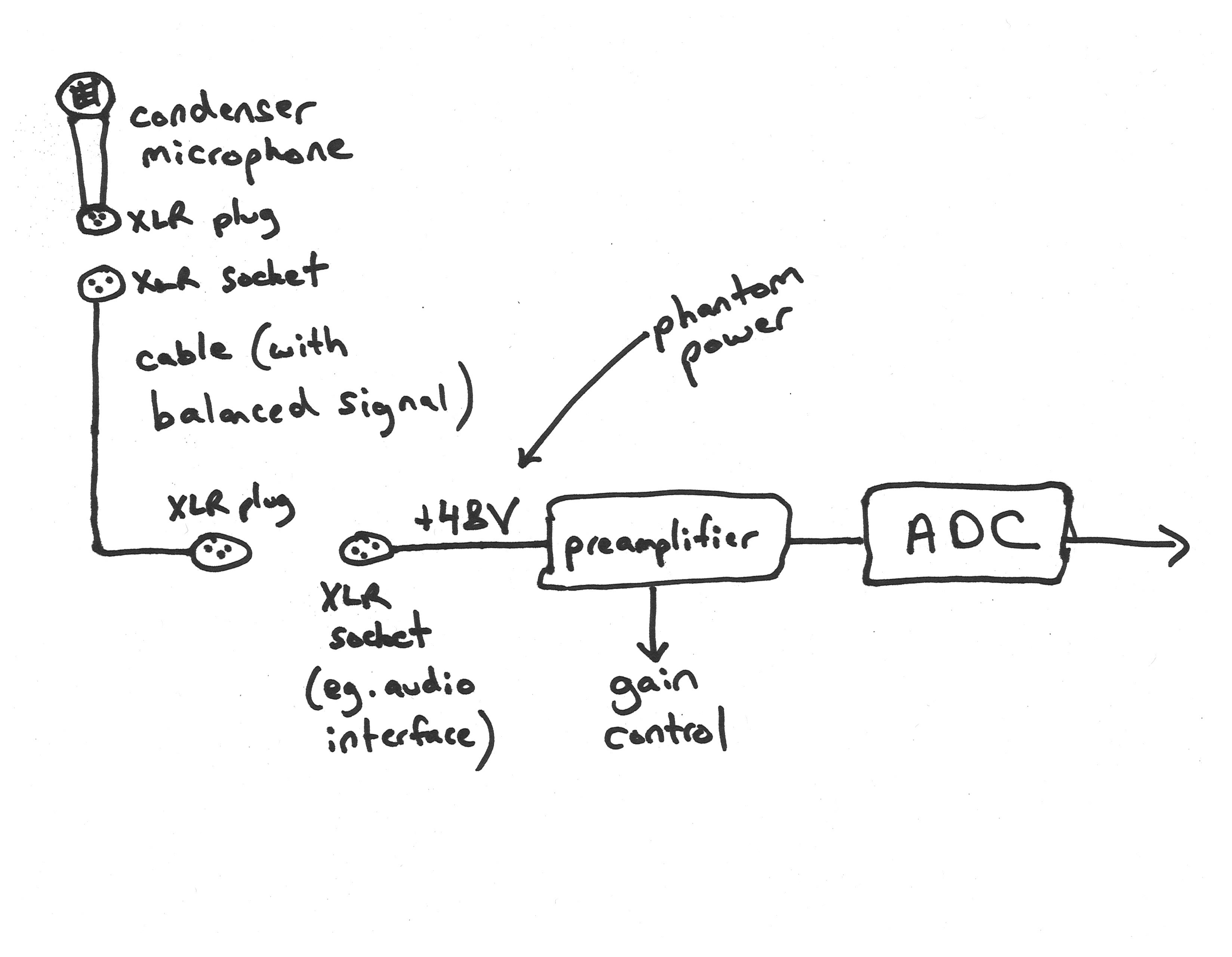
The diagram above shows an overview of a typical microphone connection. We start from a condenser microphone, and at the bottom/end of the condenser microphone we'll probably see an XLR plug with three little metal prongs. And then we'll have a microphone cable, and so we'll take the end of that cable that has a socket with the three little holes in it, and those two can go together. And then our cable has got three pieces of metal in it because we're carrying a balanced signal, and at the other end of the cable we're going to have an XLR plug again. So it's almost like the cable has extended the end of the microphone: the microphone ended in an XLR plug, and we plug in the cable, and now the end of that cable is kind of like the end of the microphone has gotten longer, it's an XLR plug again. And because it's a plug, we can connect it into a socket (such as the XLR socket on an audio interface), and probably somewhere nearby there, we'll have a button that lets us turn on phantom power. So that power is going to arrive at the microphone over this cable, and signal is going to come back to our preamplifier over the same cable. And then we have our preamplifier, there's going to be some kind of gain control, and finally the signal from all of that reaches our analog to digital converter where it's digitized and becomes available to our software, or stored on a memory card or whatever else is going on.